WarBlock Receiver Height AR15 Gas Block CNC Machining (15): first test production run
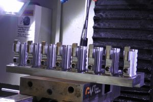
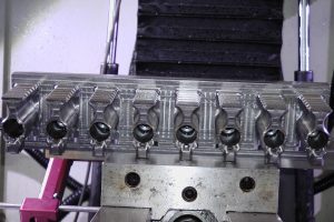
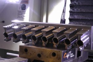
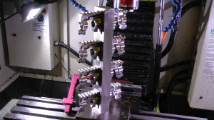
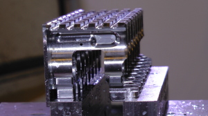
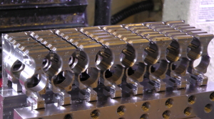
Finally after many months of work preparing for an actual production run we are now here. Before that we first knock out a little side project that I had done some work on months ago for a customer. I had worked closely with this customer on a prior successful project so I thought this would be an easy “reproduction” run. With the previous part there was a problem that required some further machining but it is good now. The material used is a carbon based alloy that is soft but difficult to work with due to being gummy. Nevertheless it went fine and with the exception a couple of sort of bumpy patches and some areas that left some fuzz had an unbelievably smooth surface finish especially on the back side. The level of detail was simply amazing. There was a lot of chatter in areas, especially at night, but it quieted down somewhat eventually. It held decent tolerances at 21.5 inches +/- 1.oooo” or so for being such a hefty part at 7lbs 6.2oz. Unfortunately I noticed that even though the tool was cool to the touch the work was quite warm and had moved a little. The customer also complained a little about residual thermal expansion as this piece grows a little dimensionally everyday and may have some stresses in it as it continues to warp and change shape. I also had a slight problem with coolant drainage. Apparently I had quite a bit of tramp collect in the bottom of the part which must have became rancid. The total op time needs to be improved on a little as it is taking a little longer than the first one at 38 weeks vs 37 with the first but is still under the estimated program run time of 40 weeks. There was a another problem with the machine overheating and puking on me but that was early on in the program and she eventually settled down. The program run finally ended at 4:49 am Sept 12, 2014.
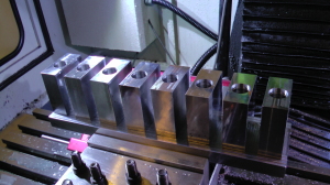
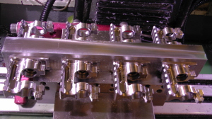
Moving along, I was never really satisfied with the way the blanks mated to the fixture plates. It seemed that the tolerances required to keep the part aligned were so tight that hitting them seemed like a matter of chance. I’m specifically talking about the main drilled bore hole and the gastube hole, those are features that align with the bosses on the fixtures and need to be snug with no play. The way I had been doing it before was basically just luck that they would be the exact right distance from one another after I flip the stack of blocks over from one op to the next. After getting a particularly bad fit on two of the test blocks I decided to rethink it. I first greatly increased the depth of the gastube hole chamfer thinking this would allow some flex in the boss by engaging it more towards its tip and make for a better fit. After trying it on a few the fit was marginally better but still not good. Let’s rethink it again, we need a repeatable bullet proof solution. The large boss is the reference point of all the gasblock geometry and machining operations so it needs to be fairly snug, and it is. The boss that goes into the gastube hole is simply for rotational alignment nothing more. I remember someone telling me to use diamond shaped bosses for rotational alignment because they are a little more forgiving of anything short of an exact match. I thought about how they work and decided that instead of modifying the fixture plates to either accept diamond boss pins, or to machine the round bosses into diamond shaped pins, I would alter the blocks slightly. If the only real purpose of these bosses is to rotationally align the part and the only real problem with them now is that the holes that mate with them are not always the exact same distance from each other as the bosses are, well then really the only important dimension is the side-to-side captivation of the boss. And thus I milled a small rectangle pocket right over the gastube hole. Now the vertical boss/hole misalignment can be as much as 0.1″ in either direction while the long sides of the rectangle pocket snugly secures the boss and prevents any rotational play. Perfect. This also had the added benefit of making donning and doffing the parts on and off the fixtures much easier.
All of the Fixture 1 operations went almost perfectly. The only issues were just CAM errors where I left a plunge feed too slow or something. The two endmills in these operations that are doing the bulk of the grunt work are the long 0.5 Lakeshore carbide rougher and the 0.375 “Fireplug” rougher of the same make. They display some great performance but have taken a beating in just one run of eight. The 0.5″ rougher sustained numerous chipped teeth and I wonder if it will make it through another run. I will try it and see but the cuts starts to get louder and the deflection climbs. The Fireplug wasn’t completely new when I started this run but it also has a lot of chipped teeth. Both of these endmills are still cutting so I will just see how long they actually last until failure. The 0.5″ rougher needs to last more than one run of 8, lasting 16 gasblocks would be acceptable, 32 to 48 would be ideal but probably unlikely. It’s one of the most expensive cutters in these ops and the longer it lasts the lower I can keep the price of the gasblock. All of my other endmills are holding up remarkably well. I did however replace the 0.1875″ endmill because the chipped flute tips from the Mach brain fart are now causing the endmill to deflect more than usual.
I replaced it with this one from Lakeshore carbide.
I think this one will last much longer given radiused flute tips. I got the least amount of radius at 0.01 to start with and even that should make a big difference.
I understand CNC parts are expensive but this project came to fruition from the perspective of me being a consumer a customer and a user. I like parts that above all work great, are reliable, over built, elegant, and also affordable. Seeing parts grossly over priced for the sake of their rarity is a decision the maker ultimately has to make, but as for myself, a believer in the unfettered free market, sees an opportunity to streamline the manufacturing and/or increase the supply to meet the demand and reduce the economic impact of scarcity thus keeping the prices in check. Otherwise you are inviting the competition to undercut you. To me exorbitant prices out of league with reasonable manufacturing costs are off putting. I have a naive vision that this gasblock will become the gold standard gasblock for the A3 and A4 flattop AR15 much as the flattop AR15 has all but replaced the A1 and A2 style fixed carry handle AR15. Making it extremely costly is a perfect way to remain obscure and, while a perfectly legitimate market practice, ultimately short sighted from a business perspective in my view. This is why if given the opportunity to invest in larger equipment and automation my ultimate intention is to increase production and make these gasblocks ubiquitous features. I’d like to see them as an evolutionary time point in the history of the AR15, casting off the vestigial traits of the previous and increasingly maladaptive generation.
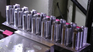
Transferring the gasblocks from fixture 1 to fixture 2 was a breeze and totally solid with the new way I was milling the rectangular boss captivation pocket in the back. Again as with fixture 1 the Fireplug is doing an inordinate amount of the material removal in fact the bulk of the material removal here on fixture 2. While it has its battle scars it still seems to cut fine. The especially concerning aspect of the long 0.5″ rougher sustaining damage in one run it that it is not used anywhere else but on fixture 1 front side. It doesn’t pull double duty anywhere else like the 0.375″ Fireplug does so its economy is somewhat fixed.
I was apprehensive about the milling on fixture 2 because so much depends on perfect alignment to get everything to cut just right and not slightly gouge the part here or leave a little too much there. The main reason for the apprehension was the fact that my Haimer 3D Taster indicator has some X and Y backlash as mentioned before and I wasn’t sure if I could completely trust it to indicate correctly. When machining one of the practice parts I noticed a somewhat significant misalignment error in the 3D contouring causing some gouging on one side of the fixture and too much material left behind on the other side between flips. I narrowed down the cause and attributed it to the Haimer backlash. When indicating the Y axis I approached the fixture from two different directions from each side of the flip. This resulted in the backlash showing up in the part. However in this production run I made sure to always approach in the same direction so as to cancel out or negate the backlash from having an effect between parts.
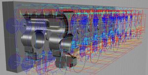
The program run times took a little longer than hoped but were also much better than I had originally anticipated. Much of this is due to the deflection caused by using those long 2.5″ stickout endmills on fixture 1 resulting in a lot of deflection and thus requiring multiple spring passes. Perhaps a more rigid machine that can handle larger diameter cutters can alleviate that. The next most time costly operations are the 3D contouring. The main issue with those operations being as long as they are is due to my spindle speed limitation. Only having 5000 available RPM really limits the feedrate that you can push small ballmill cutters. The 10,000 to 30,000 RPM spindle of a larger machine with servos could really speed that up. There are some things that I could potentially do to reduce cycle times once I get a handle on the price to performance ratio of pushing everything harder but right now I will leave it alone and just get some cooking and out on the market. I will update the cycle times of each op here when I get a more accurate time of the final procedure dialed in. I’ll mention when I do this in a future blog post so you can refer back to here if interested.
Cycle times x8 Production Run
Raw material cost x8: $72
Stock preparation (facing, squaring, etc): 58 min average per x8
Main bore and gastube hole: 51 min cycle time
Fixture 1 Front Side:
Fixture 1 Top Side:
Fixture 1 Bottom Side:
Fixture 2 Side 1:
Fixture 2 Side 2:
Back tab Milling:
You probably noticed the new vise jaws in the video. I made those for milling the final operation but I designed them to serve numerous roles. That will be detailed in the next installment.
I ran into another major problem between machining side 1 of fixture 2 and the flip to side 2. The machine computer would not boot up. Through some investigative research I discovered that the harddrive had likely failed. I have a drive rescue kit which is comprised of a device that powers any harddrive and converts it to USB, and when I powered it I could hear is was spinning slowly and clicking, not good. I did the old trick of putting the drive in the freezer, letting it get nice and cold, then powering it up. It actually sounded better but didn’t spin up fast enough. I tried toggling the power on and off to give the disc enough momentum so that it might take off. To my surprise this worked! It took about a minute of power on power off cycles before it just took off. I was able to make a disc image of it using imaging software but I also simply copied the contents of the drive over to my desktop computer. I restored the image to a new SSD I went out and bought thinking it would be more immune to the machine vibrations but it would not boot either. I spent quite a while trying to fix the master boot record and repair the boot sector using the recovery console in Windows XP. Nothing worked, the data on the drive was no doubt corrupted from the crash. Fortunately I made a disc image when I first got the machine and restored this to the SSD and everything worked fine. Of course I had to go and update all the drivers for everything, touch screen monitor, chipset, LAN, onboard graphics, etc. I also had to reinstall the latest versions of Mach3 and the ethernet smoothstepper plugin. This was all no big deal really. What was really bothering me was all my Mach settings. Well I scoured the files I was able to recover from the failed harddrive only to discover many of the files that had been open right before I shutdown the previous day were gone including my .xml settings file and my tool3.dat file containing my tool table. The crash must had deleted them. I recovered my custom screenset but some of the .jpg images were corrupted or gone. I downloaded new ones and was able to recover the backup of the current .xml I had been using in the xmlbackups folder (go figure). What confused me was that they did not have the .xml file extension but something like .16b11 instead. Turns out all you have to do is change the extension to .xml and it is the same current .xml you were using before. Wow that saved my ass from having to redo all that stuff, half of which I don’t even remember. The only thing I lost was the tool table and some hand written Gcode programs that I used frequently. I remeasured all my tool offsets, rewrote two of the Gcode programs but the 3rd was too complicated to rewrite on the fly. Then I remembered that I posted the code to the CNCzone forum a long time ago when I was trying to get help with writing it. Luckily I was able to search CNCzone and find it. Back in business. Of course I made a new drive image once I did all that in case that ever happens again.
Well I must say that everything up to this point has been an enormous undertaking and a long and difficult journey for just one guy with more on his plate than any 10 people should have to deal with but I am getting very excited with the progress. We are still not done yet. There is still much more to do so keep watching, keep reading, and I’ll keep working. Stay tuned!


