
WarBlock Receiver Height AR15 Gas Block CNC Machining (12): 3D machining side ops revisited
Welcome back. I’ve been having a difficult time keeping up with getting my blog posts out on time but rest assured I have been machining every second I can to get this process down and ready for production. I have a bit of a back log of video and writing so while the power is down for the day I get to step away from the machine and work on catching up on my laptop. This episode will be similar to the last one but with some new tweaks to try out. I also discover a problem with fixture plate 1 and have to re-machine it.
So lets dig in. I started out by modifying some of the toolpaths from the bottom to create extra clearance for when the part is moved to fixture 2 and the endmill engages from the side. I also changed the side gutting ops to use a stub length endmill rather than the standard length one I’m actually using. You’ve heard me talk about the Maritool 0.375″ rougher I’ve been using before and it has been a real trooper but it was starting to show its battle scars and I knew it would need to be replaced soon. Even though I decided to just keep on using it for testing until it broke I went ahead and re-programmed these cuts for two Z levels passes because the “Fireplug” stub I plan to replace it with only has a 0.625″ flute length instead of a 1.0″ like the standard one. My deepest depth of cut is 0.89″ but there is only one op like that, all my other cuts with this endmill are 0.4″ or less. Maybe in the future I’ll just get more tool holders and use the longer endmill here if it saves time. I was able to further eliminate some chatter areas like the slotting in the bottom op with the 0.1875″ endmill by simply increasing the feedrate a little while taking it in two passes. Widening the roundover a little more helped with the ledge issues but perhaps not enough. Also the Woodruff cuts were modified to try and eliminate the bump it pushes out of the thin side walls but again perhaps not enough.
Now that I have pretty well demonstrated the power of the spindle and for the most part am able to base my depth of cut on the maximum allowed by the part geometry, one new thing that I’m trying out is fiddling with the optimum width of cut. Before I was defaulting to 70% max width based on some things I had heard from Sandvik Coromont but I’ve always been curious about this chart posted on CNCCookbook in an article about deflection.
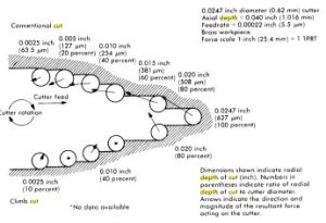
0 radial deflection when climb milling at 20% and 60% WOC
If you look you can see that conventional milling always results in radial deflection of the tool either away from the part with cuts below 50% engagement and into the part with cuts greater than 50%. However the different forces involved with climb milling result in some curious idiosyncrasies. With climb milling the tool is never deflecting into the part and is generally back driving the axis (which is why you shouldn’t climb mill on a machine with an Acme lead screw due to the backlash causing the tool to sort of violently jump back and forth during the cut). However at 2 points in the radial engagement spectrum the forces are balanced between pushing the tool away and forward and pulling the tool into the part and backwards. According to the chart these points occur and 20% and 60% radial engagement. I’m not sure if programming cuts at these widths is good or bad in terms of chatter. On one hand the deflection being absorbed rotationally or axially instead of radially may minimize chatter due to less sideways endmill deflection. On the other hand the chatter may be exacerbated by this very fact and could potentially result in the equivalent of milling right on the center line at 50% (which is to be avoided). So far the latter does not seem to be an issue. However if there truly is no radial deflection this has the potential to increase the accuracy of the cut as well as make subsequent cuts with finishing endmills easier.
The slight ringing of chatter heard in the roughing ops when side gutting are definitely from part deflection rather than tool deflection as it happens on the front leg of the gasblock that is sticking out unsupported once the center bridging material is milled away. It’s not bad and I’m not worried about it since there isn’t a whole lot I can do about it without cutting productivity.
The finishing profile using the 0.25″ endmill has never really gone well without loud screeching in those tight 0.125″ radius corners. I only want to change the model to widen those radii as a last resort so I’m trying to come up with a slick way to make those turns without chatter, preferably with the same 0.25″ endmill. I started by first trying to do it in two slow passes. That didn’t work so then I tried relieving the corners first with a series of five 0.005″ passes. That didn’t work either. So I’m either forced to use a smaller tool or plunge mill it. Since my next size smaller tool won’t cut deep enough axially I’m going to try plunge milling the little crescent of corner out before going back and profiling it. Then later in the profile cut I’ll add a small radius to the turn so that the tool avoids the very tightest part of the corner and won’t engage. The finish on the linear portions is fine but I run a spring pass anyway to make sure the dimension is as accurate as possible so that the 3D ops match up better with the geometry. I may need to lift the 3D ops off of the model a little more in future testing and if I do I could probably drop the spring pass. I also have another tool from Lakeshore Carbide I want to try after this one wears out. It is a 4fl variable flute corner radius long length 0.25″ endmill with a 1.125″ flute length. I don’t have a lot of experience with variable flute endmills but when I do use them they work phenomenally well. Usually much better than standard flute as far as chatter goes. The small radius on the tips will also enhance tool life and potentially improve the surface finish when plunging.
Lakeshore Carbide long length variable flute finishing endmill
Next I came back to the issues of the 3D toolpaths cutting too deep. After some examination I have determined that fixture plate 1 has a flaw. I mentioned before about how when I first machined it I tapped the holes after I machined the bosses causing the bosses to slightly increase in size. This forced me to re-machine them resulting in me cutting them too small. Now the fact that the bosses are too small the drilled blank fails to index properly due to some side to side play. I measured the total play to be 0.014″, in other words HUGE and completely unacceptable. So when I bolt down a blank to fixture plate 1 it maybe as much as 0.007″ off to either side. It is then machined correctly but yet cockeyed to the boss. Later when it is transferred to fixture plate 2 where is fits tight the part is now between 0.007″ too high or too low rotationally around the boss depending on it’s orientation to how it was secured on fixture plate 1. The only way to fix this issue is too re-machine the face of the fixture plate. Fortunately I could reuse the fixture plate by just buzzing off the bosses and sinking the face down 0.1″ and re-profiling new bosses to the correct size as on fixture plate 2. This worked out great and now everything fits tight. Actually a little too tight but I think increasing the depth of the hole chamfers on the blank should take care of that.
Before I made the modifications to fixture plate 1 tried the 3D machining again on a blank that happened to fit on fixture plate 1 more snugly than the first one did. This greatly improved the problem with the cuts being too deep but they are still slightly too deep. I determined that the mostly likely explanation for this other than fixture plate 1 misalignment is draft due to deflection. When doing the profile cuts with those long endmills on fixture plate 1 endmill deflection makes the part right on dimension at the top but slightly wider at the bottom. In fact with one finish pass and one spring pass still results in about 0.0025″ or so of draft from top to bottom. This consequently is about the amount that the 3D paths are cutting too deep on the back of the gasblock. The front being right on. I’ve gone back and added another spring pass to the profile resulting in a draft of only 0.001″. Not perfect but much better. In addition to the two spring passes I will also lift the 3D path up a little more to 0.001″ off the model. I may go more but we’ll see if it’s necessary.
Next I lifted the 3D path for the lightening window up off the model from 0.002″ to 0.005″ which turned out great and was even perhaps a little too much so I later turned it back down some”. Lifting the path off the model 0.004″ was perfect but with the two spring passes I might even be able to lower that to 0.003″ or maybe even less. The original toolpath here left a small divot and a slightly chattered vertical wall which doesn’t matter or hurt anything but I’m going to try and get rid of them as a matter of principle. Re-programming the toolpath a little actually made it worse so I contemplated going back to the way it was before but I can’t leave well enough alone. My motto seems to be “if it ain’t fixed, break it until it is”.
Perhaps the biggest improvement gained in this installment is the addition of arc fitting to the 3D toolpaths. When the natively generated 3D toolpaths are simply and huge series of straight lines this causes the machine to seriously slow down around curves which extends the estimated cut time by about 3x and makes the ground jitter and shake like one of those old fashion exercise machines that would wrap around your gut and shake the fat off your ass. When I was able to go in and add arc fitting (a feature of RhinoCAM Pro) I was able to speed up the whole operation and get it to cut so much more smoothly. It also greatly minimized the chatter. Those areas where it slows down reduces the chipload and increases the likelihood for chatter, by keeping it moving along at the programmed feedrate keeps a healthy chipload and make for a quieter more peaceful cut. Playing with the parameters such as tolerance, minimum arc length, and max radius arc this basically replaces the series of lines segments that make up a curvature into one or more simple arcs. It also has the added benefit of drastically shortening and simplifying your code. For example in the case of the lightening pocket the native code generated was just over 13,000 lines. With arc fitting this is reduced to about 3300.
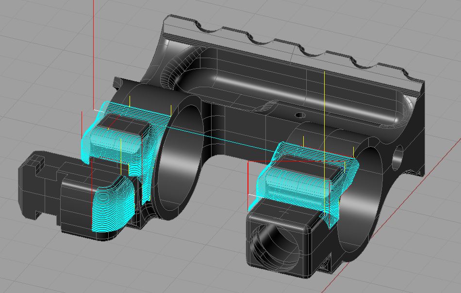
Natively generated linear toolpath

Toolpath with arc fitting (arcs in dark blue)
We end this episode with a 15x video of re-machining fixture plate 1 to fix the errors with the boss sizes. By cutting the bosses to 0.0005″ under per side (0.001″ smaller diameter) than the hole size of 0.5512″ resulted in what previously had 0.007″ of play from side to side down to 0. Unfortunately this was not the only problem with the fixtures as new ones were uncovered and rectified but I’ll save that for next time.