
WarBlock Receiver Height AR15 Gas Block CNC Machining (14): finalizing side ops
In this installment I just wanted to finish up cut testing on the side ops mainly to eliminate chatter and to improve surface finish. There is not a lot to comment on here so this will be a short blog post. However here are some things I found useful to know when troubleshooting and developing tool paths.
Raise your 3D toolpaths above the model:
This has the benefit of tailoring the 3D tool path to your actual part geometry instead of a theoretical model. Backlash, tool wear, and mostly (in my case) tool deflection all contribute to a complex workpiece that does not exactly match the computer model. The work generally ends up being slightly larger than the model I’ve found, especially if you are careful to use mainly climb cutting where the tools deflect more away from the part being cut. This means that if you generate a 3D toolpath it will cut true to the model and on an oversized part leave artifacts, tool marks, and abrupt changes in surface geometry. By simply experimenting with lifting the tool path up off of the model you can eliminate these issues and make for a better more aesthetic part. In the case of this gasblock I only needed to lift the 3D contours 0.001″ above the model to get it to blend well due to the spring passes on previous ops. On the other hand the 3D paths on the lightning window needed to be raised a full 0.005″ to blend. This is no doubt from the concave geometry causing endmill deflection on that 2.5″ long cutter despite the 2 additional spring passes.
Create operations that negate the requirement of absolute accuracy of previous ops from a different setup:
If you machine something in one fixture or setup, then move it to another fixture or setup and expect the geometry to match the new tool paths based on that geometry, you’re going to have a bad time. It can be very very close but you are walking a tight rope. As the endmill from the previous ops wears, the parts geometry will change and this change will be evident when later paths are now cutting “too deep” relative to the part even though they are cutting true to the model. Consistency suffers. Also unless the positioning of the part on the new fixture is absolutely accurate i.e. no play whatsoever this can induce minor surface inconsistencies. What I had to do was run another pass over the areas that had previously been machined from a prior setup to make sure the geometry was “aligned” or matched when in the new setup. The more independent you can make operations in a new setup from those in a previous setup the better. With this knowledge in mind you can even think about this when designing a new model in CAD.
Don’t be afraid of spring passes:
As was mentioned before endmill deflection plays a huge role in part accuracy and I have found that nearly any milling will result in some amount of deflection. What is acceptable is up to the tolerances of the part. Areas that either need to be very accurately machined or whose dimensions are critical for a future op such as 3d milling could certainly benefit from a spring pass or two, and yes even with carbide tools. Yes it takes a little longer, yes it adds a little more wear to the tool, but your parts will be more accurate, more aesthetic, and more consistent. Plus it is probably ultimately less wear and less time than if you took many more lighter less aggressive cuts to eliminate the deflection. I would say the longer the tool and the heavier the cut the more useful a spring pass is going to be. Adding 2 spring passes on top of the finish pass in the main profiling op using the long 2.5″ endmill really tightened up the geometry proper to the model and eliminated potential problems down stream.
Turn down the RPM to eliminate chatter:
This one is a no-brainer but I was surprised just how far I had to reduce RPM to get the squealing to stop, by about half in some cases. In other cases I was right on the edge of chatter. For example with the 0.25″ finish passes after the side gutting I went from 3145 to 2800 to 2450 to 1850 and it still chattered. Then going from 1850 to 1815 completely eliminated the chatter like a switch and the finish is amazing. Like Carl at Lakeshore Carbide says, once you drop the RPM to the point it stops chattering you have found the happy chipload for the cut, then you can increase the RPM and the feed accordingly, maintaining that same happy chip load. While I have found the happy chip loads, I have not speed things up yet. Perhaps I will do that later to even further optimize the process but for now I just need to make them without breaking any more tools.
Use surface planes to modify 3D ops:
If your CAD/CAM combo can do this (it should), you can add planes or surfaces to specific areas around the model to fool the program into thinking they are part of the model and thus generate tool paths around them. Simply lifting the tool path above the model by increasing the stock material value is a very two dimensional exercise. Suppose you wanted to lift the path a little in one area but not in another, copy a surface of the model then lift or tilt it upwards in the Z. Generating a 3D op around this new geometry will alter the tool path. Case in point notice how I created some planes in the image on the right to not only modify the behavior of the ballmill while still cutting the same geometry but also to create more of a gradual entry into the work piece. You can also use this technique in conjunction with containment regions to control where the tool changes direction so that it does so out side of a cut so as not to leave tool mark artifacts in the surface of the work.

3D tool paths to model with arc fitting
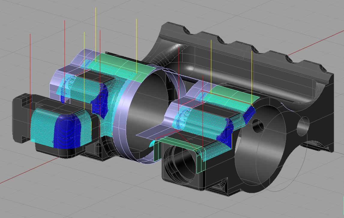
3D tool paths using containment surfaces
Use plunge milling to relieve tight corners before a profile pass:
When confronted with a corner radius that is equal to the radius of the endmill obviously the best action is to drop to a smaller radius endmill. Due to the fact that the radial engagement spikes to 50% almost instantaneously this causes a very loud chirp and will often chip the flutes of your fine finishing endmill. If you are already slotting or engaged 50% or more radially taking a hard turn wont hurt anything as the endmill is already at maximum deflection. However in some cases dropping to a smaller endmill may be impractical because the next size down may not have a long enough flute length as was the case with me forcing you to use an endmill of the same radius as the profile cut. Slowing the feed way down didn’t really help, chipping away at the corners first in very light stepovers didn’t really help either. Absent a trochoidal or high speed tool path the best solution seemed to be simply plunging the corner out. This actually worked surprisingly well and has yet to hurt the flute tips of my endmill.
Use as few Z levels as you can get away with:
Do it all in one Z level if you can. This engages more of the cutting flutes of the endmill and minimizes the amount of time the flute tips are engaged. The flute tips are the most fragile and most vulnerable part of the tool and often when they get chipped or damaged, as they typically do long before any other part of the flute, the tool stops cutting well and is trashed. Imagine cutting to a depth of 1 inch for 1 inch of travel. Taking a 0.1″ DOC results in 10 light passes or in other words 10 linear inches of cutting is imposed on the flute tips and bottom 0.1″ of the flutes. However taking a 1.0″ DOC engages the flute tips for only 1 linear inch and uses much more of the tool you paid for. Both cut geometry’s are the same but the gentle and light 0.1″ DOC is 10 times harder on the tool than the aggressive hogging at 1.0″ DOC and will potentially offer a 10x shorter tool life. Sometimes tool deflection and chatter will limit the amount of depth you can take so you may have to divide it up into 2 or more Z level passes but the goal is as few as possible. If you must sacrifice something to pull it off you should usually sacrifice width of cut to get a greater depth of cut. Again in my case I wanted to do the side gutting in one Z level but simply couldn’t due to the tool deflection of my 0.375 rougher (may it rest in peace). Now with the Lakeshore Carbide Fireplug the limiting factor is not deflection but flute length so I kept it at 2.
Don’t be afraid to slot:
Much has been said about avoiding slotting ops or where you have 100% radial engagement. While sound advice, in my experiences here sometimes I was doing far more damage to the tool by trying to avoid slotting. I was creating all kinds of funky tool paths to take multiple passes simply to avoid the dreaded slot. I was also chipping a lot of tools doing it this way. Imagine my surprise when I just said “screw it” I’m slotting and the slots ended up being the quietest and gentlest cuts I’ve ever done. The caveat is that you really need adequate coolant pressure to really clear those chips out.
Don’t be afraid to helix:
Like the slot the other dreaded op is the plunge. So logically since a helix employs both it should be feared right? Well, what I’ve found out here is that provided the helix angle is shallow enough the helix is a great way to create an accurate odd sized hole for which there is no drill size or for some other reason that precludes drilling or circular interpolation.
Always try to maintain a climb cutting condition where practical:
This just leaves a nicer finish, is easier on the tool, is more predictable as far as deflection goes, is much less likely to gouge or undercut the part, and it’s easier to clear chips from. The few times where I tried conventional milling (out of necessity) I was quite disappointed with the finish. This also should impact how you arrange the part on your fixtures. If I had known better I would have arrayed the gasblocks on the far side around the other way instead of mirroring them so I wouldn’t have to fiddle with reversing each tool path but instead just mirror and flip the whole thing and be done with it. The way I have it now the tool paths on the far side are opposite the near side so that involved quite a bit of tweaking and uncertainty to get them back to climb milling. Luckily there were no major issues. Live and learn.
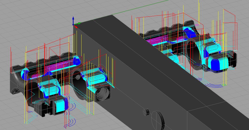
Here is a parting shot of all the side tool paths for 2 gasblocks in stations 1 and 5 of fixture plate 2
Now with all that done we are ready to begin expanding the instances of these ops and switch gears into production testing. There are very exciting things coming up next so say tuned!